Pumps are critical, but they are often monitored only when something goes wrong. A borewell pump runs dry, a transfer pump trips at night, a discharge line gets blocked, or a motor keeps running without flow. By the time the issue is noticed, water, energy, production time, or equipment life has already been lost.
Remote pump monitoring solves this by tracking flow, pressure, runtime, fault status, and connectivity continuously. This guide explains what data to collect and how to design a reliable 4G pump monitoring system.
Where remote pump monitoring is useful
Remote pump monitoring is valuable anywhere pumps operate away from constant supervision.
Common sites include:
- Borewells and groundwater extraction points
- Water treatment plants
- STP and ETP systems
- Industrial utility pumps
- Cooling tower circulation pumps
- Irrigation and agriculture pumps
- Pump houses in townships and campuses
- Remote transfer pumping stations
- Fire pump status monitoring
The goal is not only to see whether the pump is ON. The system should show whether the pump is actually moving water as expected.
What should be monitored?
A practical pump monitoring system combines electrical status, hydraulic data, and device health.
| Parameter | Why it matters |
|---|---|
| Pump ON/OFF status | Confirms runtime and duty cycle |
| Flow rate | Shows whether water is actually moving |
| Cumulative flow | Useful for usage reports and compliance |
| Discharge pressure | Detects blockage, closed valve, or abnormal load |
| Suction pressure / level | Helps detect dry run or low source condition |
| Motor current | Detects overload, underload, and electrical issues |
| Fault/trip signal | Confirms protection relay or starter trip |
| Runtime hours | Helps plan maintenance |
| Power failure | Explains data gaps and pump stoppage |
| Gateway signal strength | Shows whether telemetry is reliable |
A strong monitoring design uses more than one signal. For example, pump ON with zero flow is a different problem from pump OFF with zero flow.
Basic architecture
A standard 4G pump monitoring system looks like this:
Pump Starter / Flow Meter / Pressure Sensor
        ↓ Modbus RS485 / Digital Input / Analog Signal
Industrial IoT Gateway
        ↓ 4G LTE
Cloud Dashboard
        ↓
Reports + Alerts + Maintenance Actions
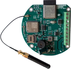
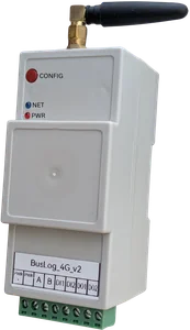
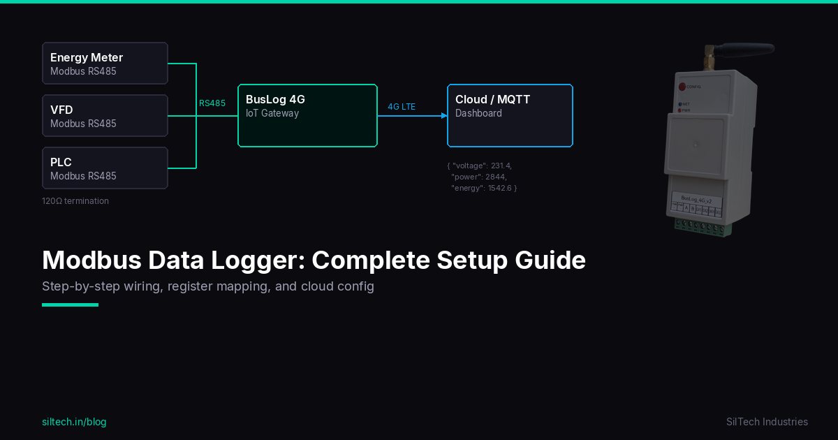
For many sites, a Modbus flow meter and pressure transmitter can be connected to a gateway such as BusLog 4G. For compact flow-meter-specific deployments, Flow Telemetry 4G can be used.
Flow monitoring
Flow is the most important parameter for water pump monitoring. It confirms that the pump is doing useful work.
Recommended flow values:
- Instantaneous flow rate
- Cumulative forward flow
- Reverse flow, where applicable
- Daily total
- Monthly total
Flow data helps answer practical questions:
- Did the pump run today?
- How much water was extracted or transferred?
- Is the pump producing less flow than usual?
- Is there flow when the pump is supposed to be OFF?
- Is there zero flow while the pump is ON?
If the application is groundwater extraction, also read the CGWA groundwater telemetry guide.
Pressure monitoring
Pressure gives important context that flow alone cannot provide.
High pressure with low flow may indicate:
- Closed valve
- Blocked filter
- Choked pipeline
- Wrong operating condition
Low pressure with low flow may indicate:
- Dry run
- Air lock
- Pump wear
- Suction problem
- Low water level
Pressure transmitters can be read through Modbus, analog input, or a signal converter depending on the site architecture. If pressure is critical, configure both warning and trip-level alerts.
Runtime monitoring
Runtime data helps with maintenance and energy analysis.
Useful runtime metrics:
- Total run hours
- Daily run hours
- Number of starts per day
- Long continuous run events
- Run time without flow
- Pump idle/offline duration
Too many starts can reduce motor and starter life. Long runtime with poor flow can indicate mechanical or hydraulic issues. Runtime reports are also useful for shift handovers and service planning.
Fault and trip alerts
A pump monitoring system should capture fault status from the starter, drive, relay, or PLC.
Common fault inputs:
- Overload trip
- Dry run trip
- Phase failure
- VFD fault
- High pressure trip
- Low level trip
- Emergency stop
- Panel door/tamper input
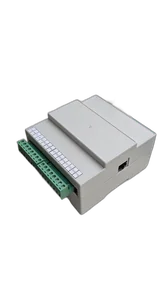
These can be connected using digital inputs or read through Modbus if the controller supports it. BusLog IO UNI is useful when the site needs more digital or analog signal flexibility.
Recommended alert logic
Do not configure alerts only on raw values. Use combined logic where possible.
| Condition | Possible meaning |
|---|---|
| Pump ON + zero flow | Dry run, valve closed, flow meter issue, coupling failure |
| Pump ON + low pressure | Suction issue, low water level, pump wear |
| Pump ON + high pressure | Blockage, closed valve, downstream restriction |
| Pump OFF + flow detected | Leakage, bypass, reverse flow, wrong status wiring |
| Flow meter offline | RS485 issue, meter power failure, wiring problem |
| Gateway offline | Power issue, SIM/network issue, antenna issue |
| Frequent starts | Control problem, pressure switch issue, leakage |
Good alert design reduces false alarms and helps the maintenance team act faster.
How often should pump data be uploaded?
For live pump monitoring, typical intervals are:
- 10–30 seconds for critical pumps and alarms
- 1 minute for operational dashboards
- 5 minutes for routine monitoring
- 15 minutes for reporting-focused systems
If the site is remote and runs on battery or solar, the interval can be optimized. For grid-powered pump panels, more frequent monitoring is usually practical.
Local storage is important
Remote pump houses often have unstable mobile coverage. The gateway should store readings locally when 4G is down and upload them after the network returns.
Without local buffering, reports will show missing data even if the pump and meter were working correctly. For compliance and operations, this creates confusion.
A good gateway should show:
- Last successful upload time
- Number of buffered records
- Signal strength
- Device restart events
- Meter communication status
Commissioning checklist
Before handover, verify these points:
- Pump ON/OFF status matches the physical starter.
- Flow rate on dashboard matches the meter display.
- Cumulative flow matches the meter totalizer.
- Pressure value matches local gauge or transmitter output.
- Fault input changes correctly when simulated.
- Gateway reconnects automatically after power restart.
- Data buffers during network loss and uploads after recovery.
- Alerts reach the correct maintenance contact.
- Reports show correct site and pump names.
- Antenna position gives stable signal after panel door is closed.
Which SilTech device should you use?
Use Flow Telemetry 4G when the main requirement is flow meter telemetry for water or borewell applications.
Use BusLog 4G when the pump system includes Modbus flow meters, pressure instruments, energy meters, or PLC/VFD data.
Use BusLog IO UNI when the panel needs multiple digital inputs, outputs, or additional signal flexibility.
Explore SilTech’s Water & Flow Monitoring Solution for pump, borewell, and utility monitoring use cases.
Final advice
Pump monitoring should not stop at ON/OFF status. A reliable system combines flow, pressure, runtime, fault status, and gateway health. That combination tells the real story: whether the pump ran, whether it moved water, whether it operated in a healthy range, and whether the telemetry system remained online.