Industries using groundwater need more than a flow meter on a pipe. For many sites, CGWA compliance now means continuous telemetry: flow data must be captured from the meter, transmitted reliably to a cloud platform, stored securely, and made available for reporting.
This guide explains what a practical CGWA groundwater telemetry system needs, what data should be collected, how 4G telemetry works, and what to check before commissioning a site.
Note: CGWA requirements can vary by NOC condition, site category, and the latest notification. Always confirm the current requirement for your industry and location. This article is a practical engineering guide, not legal advice.
What is CGWA groundwater telemetry?
CGWA groundwater telemetry is a remote monitoring system for borewell or groundwater extraction points. Instead of relying only on manual readings, the system automatically records water extraction data and sends it to a cloud dashboard.
A typical setup includes:
- Digital flow meter on the borewell or discharge line
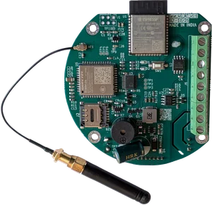
- Telemetry gateway with 4G connectivity
- Modbus RS485 communication between meter and gateway
- Local storage for network failure periods
- Cloud dashboard for reports and alerts
- Tamper and communication-loss monitoring
For industries, the goal is simple: prove how much groundwater is extracted, when it was extracted, and whether the telemetry system remained active.
Why manual readings are not enough
Manual meter readings have three common problems:
- They are not continuous — readings may be taken daily, weekly, or monthly, but extraction happens every hour.
- They are difficult to verify — paper logs can be missed, delayed, or entered incorrectly.
- They do not show system health — if the meter, gateway, SIM, or power supply fails, the issue may go unnoticed.
Telemetry solves this by creating automatic timestamped records. It also helps operators detect abnormal flow, pump runtime issues, reverse flow, zero-flow conditions, and communication failures.
Core components of a CGWA telemetry system
1. Digital flow meter
The flow meter is the source of truth for water extraction data. In most industrial installations, an electromagnetic or ultrasonic flow meter is used.
Important meter capabilities:
- Cumulative forward flow totalizer
- Reverse flow or net flow totalizer, where applicable
- Instantaneous flow rate
- Modbus RTU communication over RS485
- Stable accuracy over the required operating flow range
- Meter serial number and calibration documentation
The telemetry gateway should read data directly from the meter over Modbus, not depend on manual entry.
2. Telemetry gateway
The gateway collects meter data and sends it to the cloud. For remote borewells and industrial utility areas, 4G is usually preferred because LAN or WiFi is often unavailable.
A suitable telemetry gateway should support:
- Modbus RTU over RS485
- 4G LTE connectivity
- MQTT, TCP, or HTTPS data upload
- Local data buffering during network failure
- Configurable upload interval
- Remote configuration support
- Device health and signal diagnostics
- Tamper and power-loss event reporting
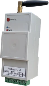
SilTech’s Flow Telemetry 4G and BusLog 4G are designed for this kind of flow meter and groundwater telemetry deployment.
3. Cloud dashboard
The dashboard should show live data, historical reports, and device health. For compliance, the dashboard should make it easy to export reports and investigate missing data.
Useful dashboard views include:
- Today’s extraction
- Monthly cumulative extraction
- Flow rate trend
- Pump runtime or digital input status
- Device online/offline status
- Last data received timestamp
- Communication loss history
- Tamper or power failure events
What data should be captured?
A groundwater telemetry system should capture both process data and device health data.
| Data point | Why it matters |
|---|---|
| Flow rate | Shows current extraction rate and abnormal flow conditions |
| Cumulative forward flow | Main extraction record for reporting |
| Reverse flow / net flow | Useful where reverse flow is possible or required by meter configuration |
| Pump ON/OFF status | Helps calculate runtime and detect pumping without expected flow |
| Meter serial number / borewell ID | Links data to the correct extraction point |
| Timestamp | Proves when the reading was captured |
| Gateway battery/power status | Shows power interruptions or tamper events |
| Network signal strength | Helps diagnose unreliable uploads |
| Last communication time | Confirms whether the system is alive |
| Local buffer status | Shows whether data is safely stored during network outages |
For a strong implementation, every data packet should identify the site, borewell, meter, gateway, and timestamp.
Recommended telemetry architecture
A reliable CGWA telemetry setup should follow this flow:
Flow Meter
   ↓ Modbus RS485
Telemetry Gateway
   ↓ 4G LTE / MQTT / HTTPS
Cloud Server
   ↓
Dashboard + Reports + Alerts
The gateway should continue reading the flow meter even when the mobile network is temporarily unavailable. During network failure, data should be stored locally and uploaded once connectivity returns.
This store-and-forward design is important because many borewell and utility installations have weak or unstable signal conditions.
How often should data be transmitted?
The correct upload interval depends on the site requirement, dashboard use case, and NOC condition. For engineering reliability, it is better to configure a system that can transmit more frequently than the minimum reporting requirement.
Common intervals:
- 10 seconds to 1 minute — live operations and alarms
- 5 minutes — practical monitoring and trend analysis
- 15 minutes — reporting-oriented monitoring
- Hourly — low-data periodic reporting
A 4G telemetry gateway with configurable intervals gives flexibility. If requirements change later, the site should not need hardware replacement.
Alerts that should be configured
Telemetry is most useful when it does not only collect data, but also alerts the right people when something is wrong.
Recommended alerts:
- No data received — gateway stopped sending data.
- Meter communication failure — gateway is online but cannot read the flow meter.
- Zero flow while pump is ON — possible dry run, valve issue, meter fault, or pump problem.
- Unexpected flow while pump is OFF — possible leakage, bypass, or incorrect wiring.
- Reverse flow detected — possible piping or process issue.
- Power failure — telemetry device lost supply.
- Low 4G signal — uploads may become unreliable.
- Tamper event — enclosure opened, wiring disturbed, or device restarted unexpectedly.
These alerts reduce compliance risk and also help the maintenance team fix problems before reports show gaps.
Installation checklist for CGWA telemetry
Before commissioning, verify these points on site.
Flow meter checks
- Meter is installed in the correct pipe direction.
- Required straight pipe length is maintained before and after the meter.
- Meter is properly grounded as per manufacturer instructions.
- Meter display shows stable flow and totalizer readings.
- Modbus address, baud rate, parity, and register map are available.
- Meter serial number is recorded.
RS485 wiring checks
- A/B polarity is correct.
- Shielded twisted pair cable is used where electrical noise is expected.
- Cable is routed away from VFDs, contactors, and power cables.
- Daisy-chain topology is used, not star wiring.
- 120Ω termination is used where required.
- Common reference/grounding is handled properly.
Gateway checks
- Gateway reads live Modbus values from the meter.
- 4G signal strength is acceptable at the installation point.
- SIM data plan is active.
- Device time is synchronized.
- Local storage is enabled.
- Upload interval is configured.
- Device ID, site ID, and borewell ID are correct.
Cloud checks
- Dashboard shows live readings.
- Historical trend is visible.
- Alerts are configured and tested.
- Reports can be exported.
- User roles are assigned correctly.
- Data continues after gateway restart.
Common mistakes to avoid
Mistake 1: Using a meter without Modbus output
Pulse output can work for some applications, but Modbus gives richer data: totalizer, flow rate, diagnostics, and sometimes meter health. For compliance-grade telemetry, a digital communication interface is usually easier to audit and maintain.
Mistake 2: Ignoring 4G signal quality
A gateway may work during testing but fail after the enclosure door is closed or the antenna is placed inside a metal panel. Always check signal strength in the final mounted position.
Mistake 3: No local storage
If the gateway cannot buffer readings during network downtime, the report will have missing periods. Local storage is essential for industrial telemetry.
Mistake 4: Wrong Modbus register mapping
Flow meters from different manufacturers use different register maps and byte orders. Always validate the dashboard value against the meter display before handover.
Mistake 5: No alert ownership
Alerts are only useful if someone is responsible for acting on them. Assign owner roles for maintenance, compliance, and management.
Example: Borewell telemetry data packet
A typical telemetry payload may look like this:
{
  "site_id": "factory-jaipur-01",
  "borewell_id": "bw-02",
  "meter_serial": "FM2026-1187",
  "timestamp": "2026-05-31T08:00:00+05:30",
  "flow_rate_m3h": 12.4,
  "total_forward_m3": 18452.7,
  "total_reverse_m3": 0.0,
  "pump_status": "ON",
  "gateway_signal": -72,
  "power_status": "NORMAL"
}
The exact format depends on the cloud platform, but the principle remains the same: each reading should be traceable to the correct site, meter, and time.
Which SilTech device should you use?
Use Flow Telemetry 4G when the main requirement is flow meter integration and compact telemetry for water applications. It is designed for flow meter and water monitoring use cases.
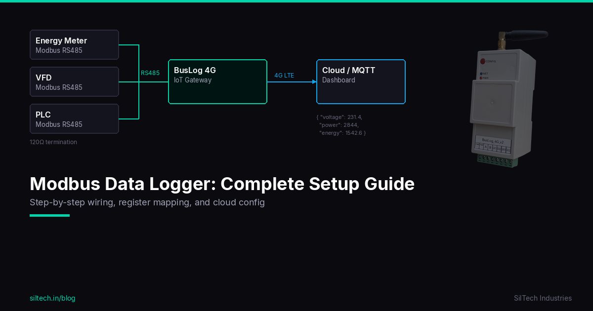
Use BusLog 4G when the site needs broader industrial data logging: multiple Modbus devices, energy meters, PLCs, VFDs, sensors, or additional digital I/O.
For water and groundwater projects, SilTech can support both simple single-meter telemetry and larger multi-site monitoring systems.
Explore the full Water & Flow Monitoring Solution.
Final commissioning test
Before the site is handed over, run this final test:
- Compare dashboard flow rate with the physical meter display.
- Compare dashboard totalizer with the physical meter totalizer.
- Switch off the meter or disconnect RS485 temporarily and confirm an alert is generated.
- Disable mobile data or remove antenna temporarily and confirm local buffering works.
- Restore connectivity and confirm buffered data uploads.
- Restart the gateway and confirm data resumes automatically.
- Export a sample report and verify site, borewell, and meter details.
If all seven checks pass, the telemetry system is much more likely to operate reliably after installation.
Conclusion
CGWA groundwater telemetry is not just about sending a number to a dashboard. A dependable system needs the right flow meter, correct Modbus wiring, 4G connectivity, local storage, cloud reporting, alerts, and a proper commissioning process.
For industries, the best telemetry system is the one that keeps working quietly every day — and clearly shows when something needs attention.
SilTech builds industrial 4G telemetry devices for water, flow, energy, and remote monitoring applications. If you are planning a groundwater telemetry installation, start with the site meter list, borewell details, and reporting requirement, then choose the gateway and dashboard architecture around that.