Diesel generator sets are often treated as backup equipment until they fail during an actual power cut. The generator may have low fuel, weak battery voltage, overload history, poor runtime records, or unresolved controller alarms — but nobody sees the issue until the site is already down.
Remote DG set monitoring solves this by collecting generator controller data and sending it to a cloud dashboard over 4G. This guide explains what to monitor, how Modbus integration works, and how to design useful alerts.
Why monitor DG sets remotely?
DG sets are used in factories, telecom sites, warehouses, hospitals, commercial buildings, construction sites, pump stations, and remote infrastructure. Many of these sites do not have a full-time electrical engineer standing next to the panel.
Remote monitoring helps teams answer:
- Is the DG available for the next power failure?
- How many hours did it run this week?
- Was it overloaded?
- Did it trip?
- Is the battery healthy?
- Is fuel consumption abnormal?
- Did the site run on DG longer than expected?
- Which location needs maintenance first?
The value is not only live visibility. It is also historical data for service planning, fuel accountability, and uptime improvement.
What data should be monitored?
A useful DG monitoring system should capture electrical, engine, fuel, and alarm data.
| Parameter | Why it matters |
|---|---|
| DG running status | Confirms actual generator operation |
| Runtime hours | Maintenance scheduling and usage reports |
| Voltage and current | Load condition and phase health |
| Frequency | Generator output stability |
| kW / kVA / power factor | Load analysis and capacity planning |
| Fuel level | Refilling, theft detection, and runtime planning |
| Battery voltage | Start failure prevention |
| Coolant temperature | Overheating detection |
| Oil pressure | Engine protection |
| Controller alarms | Fast response to trips and warnings |
| Mains available status | Understand grid outage duration |
The exact data depends on the DG controller model. Many controllers support Modbus RTU or Modbus TCP.
Typical architecture
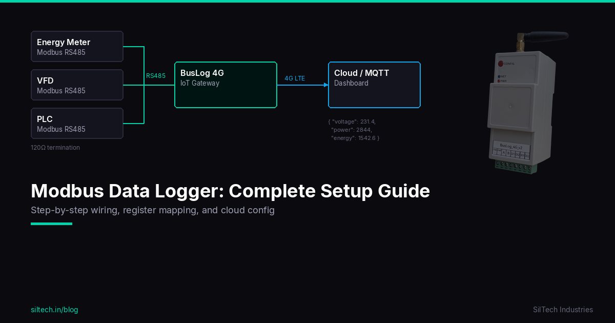
A standard remote DG monitoring setup looks like this:
DG Controller / Energy Meter / Fuel Sensor
        ↓ Modbus RS485 / Digital Input / Analog Signal
Industrial IoT Gateway
        ↓ 4G LTE
Cloud Dashboard
        ↓
Alerts + Reports + Maintenance Planning
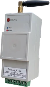
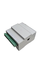
BusLog 4G can read Modbus data from controllers, meters, and sensors, then send it to a cloud platform over 4G. If the site needs more I/O signals, BusLog IO UNI can be considered.
Modbus integration with DG controllers
Many DG controllers expose parameters through Modbus registers. The gateway polls those registers at a configured interval.
Before integration, collect:
- Controller make and model
- Modbus slave ID
- Baud rate and parity
- Register map
- Data type for each parameter
- Scaling factor
- Alarm bit definitions
- RS485 terminal details
During commissioning, always compare dashboard values with the controller display. Voltage, frequency, runtime, and alarm status should match before handover.
Runtime and maintenance tracking
Runtime hours are one of the most useful DG metrics. They help schedule:
- Oil change
- Filter replacement
- Battery inspection
- Load testing
- General service visits
A dashboard can show daily runtime, monthly runtime, and cumulative runtime. If the generator runs unusually long, the team can investigate grid supply issues or abnormal load conditions.
Runtime reports also help detect unnecessary DG operation after mains power returns.
Fuel monitoring
Fuel is a major operating cost. Depending on the site, fuel can be monitored using:
- Controller fuel level data
- Analog fuel level sensor
- Ultrasonic tank level sensor
- Manual refill entries combined with runtime/load data
Useful fuel alerts:
- Low fuel level
- Sudden fuel drop
- Fuel level not increasing after refill entry
- High consumption compared to load
- Long DG runtime with low fuel reserve
Fuel monitoring is especially useful for remote sites where physical checks are infrequent.
Battery voltage and start readiness
A DG set can be mechanically healthy but still fail to start because of weak battery voltage. Battery monitoring is simple but valuable.
Track:
- Battery voltage at rest
- Voltage during start attempt, if available
- Charger status
- Low battery alarm
- Failed start alarm
A low battery alert before the next outage can prevent a site downtime event.
Fault and alarm monitoring
DG controllers provide warnings and shutdown alarms. These may include:
- Low oil pressure
- High coolant temperature
- Overspeed
- Underspeed
- Overload
- Low fuel
- Emergency stop
- Failed to start
- Battery low
- Charger failure
- Alternator fault
Some alarms are available as Modbus bits. Others may be wired as digital inputs. A good monitoring design should capture both controller data and hardwired critical signals when required.
Recommended alerts
Configure alerts that are actionable, not noisy.
| Alert | Action |
|---|---|
| DG failed to start | Send technician immediately |
| Low fuel | Plan refill before next outage |
| Battery low | Inspect charger/battery |
| Overload | Reduce load or upgrade capacity |
| High temperature | Check coolant, radiator, airflow |
| Low oil pressure | Stop and inspect engine |
| DG running too long | Check mains supply and ATS logic |
| Gateway offline | Check power, SIM, or antenna |
| Controller communication failed | Check RS485 wiring or controller power |
The alert should include site name, DG ID, timestamp, and the last known values.
Upload interval and data usage
For most DG monitoring applications:
- 10–30 seconds is useful when DG is running.
- 1–5 minutes is practical for normal status monitoring.
- Event-based uploads should happen immediately for alarms.
A smart configuration can send frequent data during running condition and lower-frequency status while idle. This reduces data usage without losing important events.
Local storage during network failure
DG rooms and remote sites may have weak mobile signal. The gateway should buffer data when 4G is unavailable and upload after recovery.
This is important for:
- Runtime reports
- Fuel usage analysis
- Fault history
- Maintenance audit trails
Without local storage, network outages create blind spots exactly when the site may be under stress.
Commissioning checklist
Before handover, verify:
- Gateway reads controller data over Modbus.
- Dashboard values match the DG controller display.
- Running status changes correctly.
- Mains available status is correct, if used.
- Alarm status changes correctly during simulation.
- Fuel value is calibrated.
- Battery voltage is accurate.
- Data resumes after gateway restart.
- Local buffering works during network loss.
- Alerts reach the right users.
Which SilTech device should you use?
Use BusLog 4G for Modbus-based DG monitoring where controller data, energy values, and cloud connectivity are needed.
Use BusLog IO UNI when the DG panel has multiple hardwired signals, digital inputs, outputs, or analog sensors in addition to Modbus.
For multi-site DG monitoring, SilTech gateways can send data to cloud dashboards over 4G without needing plant LAN, VPN, or static IP.
Final advice
A DG set is backup equipment, but its monitoring should not be an afterthought. Track runtime, load, fuel, battery, alarms, and communication health. With Modbus and 4G telemetry, maintenance teams can see problems before the next outage exposes them.