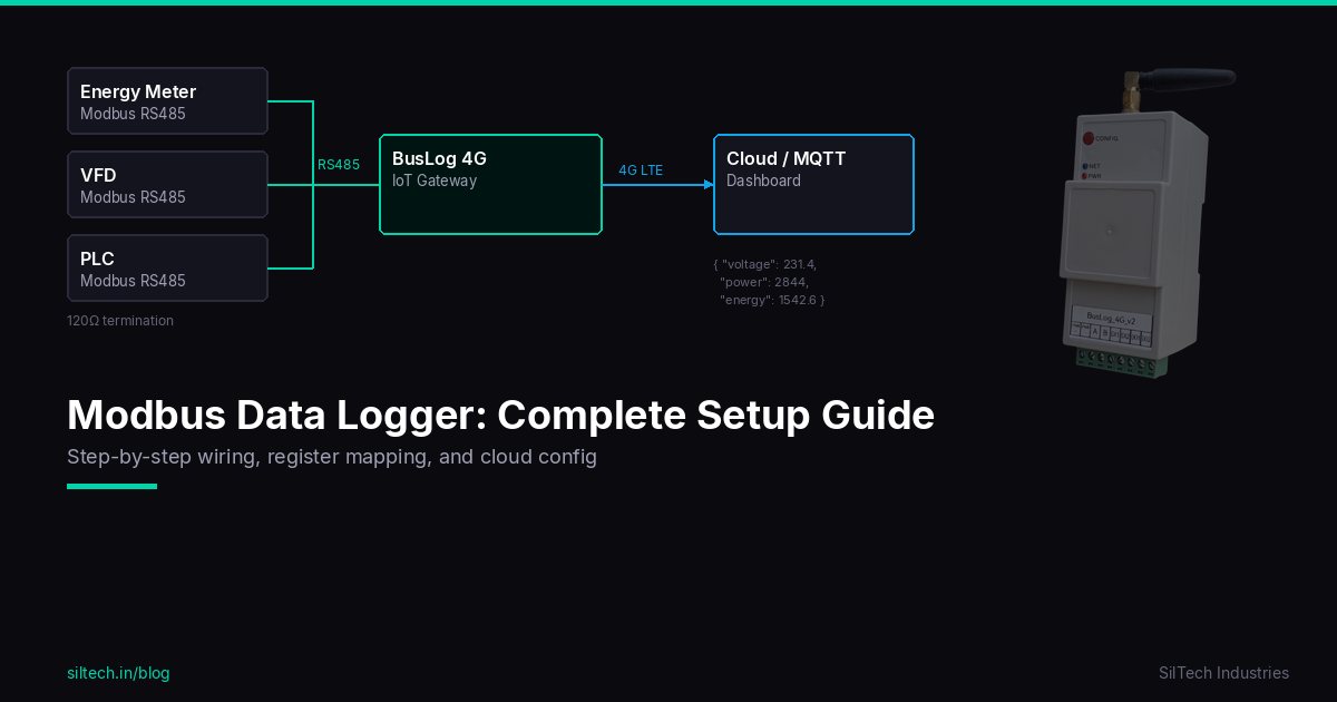
Variable frequency drives are everywhere — pumps, fans, compressors, conveyors. They're also the first thing that trips when something goes wrong on the floor. Most VFDs have a Modbus RTU port sitting idle on the back. This guide shows you how to wire it up, map the registers, and get real-time VFD data into your cloud dashboard over 4G.
We'll use ABB ACS550 as the primary example (extremely common in Indian industry), with notes for Schneider ATV and Danfoss FC series.
What You Can Monitor
Before you wire anything, understand what data is actually available via Modbus on a VFD:
| Parameter | Why It Matters |
|---|---|
| Output Frequency (Hz) | Motor speed, process throughput |
| Output Current (A) | Load monitoring, overload prediction |
| Output Voltage (V) | Drive health, power quality |
| Motor RPM | Process speed, pump efficiency |
| Run / Stop status | Uptime tracking, cycle counting |
| Active Fault Code | Remote fault detection, faster maintenance |
| Drive temperature | Thermal protection monitoring |
| Power (kW) | Energy consumption per drive |
| Operating hours | Maintenance scheduling |
| DC Bus Voltage | Drive health indicator |
These aren't theoretical — they're what separates reactive maintenance from predictive maintenance. A current spike trending upward over three weeks is a bearing warning. A fault code at 3 AM tells you exactly why the line stopped without waiting for a technician to check the keypad.
Enabling Modbus on the VFD
Most VFDs ship with the RS485 port disabled. You need to configure it from the keypad before anything else.
ABB ACS550 / ACS310 Setup
The ACS550 has a built-in RS485 port (terminals SCR, SDA, SDB on the control board).
| Parameter | Value | Description |
|---|---|---|
| P9802 | 1 (Standard) | Activate Modbus protocol |
| P5303 | 1–247 | Set Modbus slave address |
| P5304 | 9600 / 19200 / 38400 | Baud rate |
| P5305 | 0 (8N1) or 1 (8E1) | Parity / stop bits |
| P5306 | 10–1000 ms | Communication timeout |
After saving parameters, cycle power to the drive. The DRIVE LED should stop flashing once Modbus is active.
Schneider ATV312 / ATV32
The ATV series uses the same RS485 physical port but calls its settings differently:
| Parameter | Path | Value |
|---|---|---|
| Modbus address | COM → Add |
1–247 |
| Baud rate | COM → tBr |
19200 recommended |
| Stop bits | COM → StBt |
1 |
| Parity | COM → PrtY |
None (nO) |
Danfoss FC Series (FC51, FC102, FC302)
Danfoss supports Modbus via the RS485 terminal on the control card (terminals 68, 69, 61 for A, B, GND).
| Parameter | Description |
|---|---|
| 8-30 | Protocol = FC (Modbus RTU) |
| 8-31 | Address (1–126) |
| 8-32 | Baud rate |
| 8-33 | Parity / stop bits |
Wiring RS485
VFDs generate significant EMI. Your wiring has to be clean.
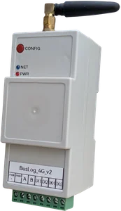
BusLog 4G               VFD Control Board
  RS485_A ────────────── SDA (or A/D+)
  RS485_B ────────────── SDB (or B/D-)
  GND ────────────────── SCR / GND
Critical rules for VFD environments:
- Use shielded twisted pair cable — minimum CAT5, dedicated RS485 cable (Belden 9841 or equivalent) for noisy sites
- Ground the shield at ONE end only — typically at the gateway side; floating at the VFD side prevents ground loops
- Physical separation — route your RS485 cable at least 30cm away from power cables. Cross power cables at 90° only
- 120Ω termination — at the last device if bus length > 50m. On ABB ACS550, there's a built-in termination switch (SW1) on the option board
- Ferrite core — clip one on the RS485 cable near the VFD if you see intermittent communication errors
If you're monitoring multiple VFDs on one RS485 bus, daisy-chain them:
BusLog ──── VFD#1 (ID=1) ──── VFD#2 (ID=2) ──── VFD#3 (ID=3)
                                                     │
                                                   120Ω (last device)
Max 31 drives per bus segment (standard RS485 driver load). Use a repeater if you need more.
ABB ACS550 Register Map
ABB uses Modbus Function Code 03 (Read Holding Registers) for most parameters. Addresses are 1-indexed in the manual but 0-indexed in Modbus frames.
| Parameter | Manual Register | Modbus Address (0-indexed) | Scale | Unit |
|---|---|---|---|---|
| Output Frequency | 1 | 0 | ×0.01 | Hz |
| Motor Speed | 2 | 1 | ×1 | RPM |
| Output Current | 3 | 2 | ×0.1 | A |
| Motor Torque | 4 | 3 | ×0.1 | % |
| Motor Power | 5 | 4 | ×0.1 | % |
| DC Bus Voltage | 6 | 5 | ×1 | V |
| Output Voltage | 7 | 6 | ×1 | V |
| Drive Temperature | 8 | 7 | ×1 | °C |
| Drive kWh (total) | 50 | 49 | ×10 | kWh |
| Active Fault Code | 58 | 57 | — | fault# |
| Drive Status Word | 43 | 42 | — | bitfield |
Decoding the Status Word (Register 42):
| Bit | Meaning |
|---|---|
| Bit 0 | Ready |
| Bit 1 | Running |
| Bit 2 | Fault active |
| Bit 3 | Fault reset needed |
| Bit 5 | Emergency stop |
| Bit 7 | Warning active |
| Bit 11 | Run requested |
Read register 42, check bit 2 — if set, you have an active fault. Read register 57 for the fault code, look it up in the manual.
Common ABB ACS550 Fault Codes:
| Code | Fault | Likely Cause |
|---|---|---|
| F0001 | Overcurrent | Load jam, motor fault, too-short accel ramp |
| F0002 | DC Overvoltage | Load is regenerating, regen into the DC bus |
| F0003 | Device overtemperature | Ambient too hot, cooling fan failure, blocked vents |
| F0006 | DC Undervoltage | Input power quality, input fuse blown |
| F0009 | Motor overtemperature | Motor overloaded, poor ventilation |
| F0014 | Earthfault | Motor or cable insulation failure |
| F0022 | Brake transistor fault | Brake resistor issue |
| F0020 | AI low (Analog input loss) | Speed reference signal cable disconnected |
Gateway Configuration (BusLog 4G)
In the BusLog web UI, configure a Modbus RTU poll task:
Port:         RS485
Baud Rate:    9600 (match VFD setting)
Parity:       None
Stop Bits:    1
Device ID:    1 (or whatever you set on the VFD)

Poll interval: 30 seconds (or as needed)

Registers to read:
  - FC03, Start=0, Count=8    → reads output freq, RPM, current, torque, power, DCbus, voltage, temp
  - FC03, Start=42, Count=16  → reads status word and fault codes
  - FC03, Start=49, Count=1   → energy (kWh)
The BusLog will format these into JSON and publish via MQTT on your configured interval:
{
  "device_id": "vfd_pump_01",
  "ts": 1745000000,
  "output_hz": 48.50,
  "motor_rpm": 1455,
  "output_current_a": 12.3,
  "motor_power_pct": 78.5,
  "dc_bus_v": 560,
  "drive_temp_c": 42,
  "status_word": 1027,
  "active_fault": 0,
  "total_kwh": 14820
}
Set up alerts in your cloud dashboard: fault ≠ 0, current > 90% of rated, temperature > 70°C.
Useful Automations
Once data is in the cloud, you can set up:
Overload prediction: Plot current vs time. A motor drawing 15A against a 12A nameplate rating that gradually increased over 2 weeks is a bearing warning.
Run hour tracking: Status bit 1 (Running) toggles. Count seconds it's high. Maintenance at 5,000 hours instead of calendar-based.
Fault log: Any time fault code changes from 0, log timestamp + code. You now have a fault history that persists even after someone hits reset on the keypad.
Energy sub-metering: Per-drive kWh tracking. Find out which motor is the energy hog.
Troubleshooting
No response from VFD: - Verify Modbus is enabled in the VFD parameters (most common mistake) - Check baud rate and parity match on both ends - Confirm slave ID is correct - Try swapping A and B — ACS550 labelling sometimes confuses people
CRC errors intermittently: - Shield not grounded, or grounded at both ends (ground loop) - RS485 cable running parallel to VFD power output cable — reroute - Add termination resistor at the far end
Reads work but values look wrong: - Check the scaling factor — ABB stores frequency as integer (×0.01 Hz), so 4850 → 48.50 Hz - Confirm you're reading from correct register block (manual register vs 0-indexed Modbus address differ by 1)
Drive throws communication fault (F0002, F0022 etc.) when Modbus is connected: - VFD is configured to trip on communication loss. Set the communication timeout parameter (P5306 on ACS550) to 0 (disabled) unless you specifically want this behaviour
Modbus RS485 is built into virtually every modern VFD. Once you know the register map, you have a window into every motor on your plant floor — not just when it breaks, but before it does.