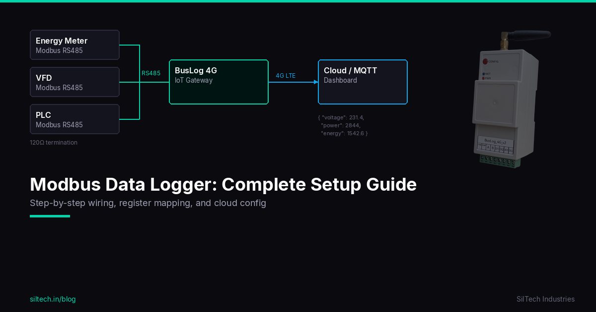
You have industrial equipment — energy meters, VFDs, PLCs, flow meters — all talking Modbus RS485. You want that data logged, time-stamped, and accessible remotely. This guide walks through the complete setup from wiring to cloud data.
What is a Modbus Data Logger?
A Modbus data logger is a device that periodically reads registers from one or more Modbus slave devices, stores the readings with timestamps, and transmits them to a server or cloud platform.
In industrial settings, this replaces manual log sheets, eliminates transcription errors, and gives you historical trends and remote visibility — without replacing your existing equipment.
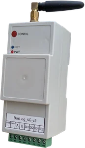
The BusLog 4G is built for exactly this: it acts as the Modbus master, polls your slaves on a configured schedule, and pushes data to the cloud over WiFi or 4G LTE.
What You Need
- BusLog 4G gateway (or BusLog 4G for sites with digital I/O)
- RS485 cable (twisted pair, 120Ω termination resistor)
- 9–24V DC power supply
- SIM card (any Indian operator — Airtel, Jio, Vi)
- Laptop or phone to access the web UI
- Access credentials for your cloud/MQTT broker
Step 1: Understand Your Modbus Slave Devices
Before touching any wiring, collect this information for each device you want to log:
| Parameter | Where to find it |
|---|---|
| Device address (slave ID) | DIP switch, label, or configuration menu |
| Baud rate | Datasheet or configuration menu |
| Parity | Datasheet (usually None or Even) |
| Register type | Datasheet — Holding (4x), Input (3x), Coil (0x), Discrete Input (1x) |
| Register addresses | Datasheet — the specific registers for the values you need |
| Data type | 16-bit int, 32-bit float, etc. |
| Byte order | Big-endian or little-endian (for 32-bit values) |
Most industrial devices have a Modbus register map in their manual. For popular devices like Schneider, ABB, Selec, and L&T meters — the BusLog has a built-in profile library. You may not need to look up registers at all.
Step 2: Wire the RS485 Bus
RS485 uses two wires — A (positive) and B (negative).
Topology: Daisy chain. Run one cable from the gateway to device 1, then from device 1 to device 2, and so on. Do not use a star topology — stubs cause signal reflections and communication errors.
Termination: Place a 120Ω resistor across A and B at the last device in the chain. The BusLog has an internal termination resistor that can be enabled via the web UI for the gateway end.
Ground: Connect the signal ground (GND) of all devices to a common reference. In noisy environments (near VFDs or motors), use shielded cable and connect the shield to ground at the gateway end only.
Cable length: Up to 1200m at 9600 baud. Shorter is always better.
[BusLog 4G] ---A/B--- [Device 1] ---A/B--- [Device 2] ---A/B--- [Device 3] [120Ω]
Step 3: Power On and Access the Web UI
Power the BusLog with 9–24V DC. On first boot it starts in Access Point mode.
- On your laptop/phone, connect to WiFi network:
BusLog_AP-XXXXXX(password: refer to your device manual for default credentials) - Open browser → go to the gateway web UI (refer to your device manual for the default IP)
- Login with default credentials (refer to your device manual)
Step 4: Configure Network (WiFi or 4G)
WiFi: - Go to Network Settings → WiFi - Enter your site WiFi SSID and password - Save and reconnect
4G (SIM): - Insert SIM before powering on - BusLog auto-detects APN for Indian operators - If using a custom APN, enter it under Network → SIM Settings
Failover: Configure both WiFi and 4G. The device uses WiFi as primary and automatically switches to 4G when WiFi is unavailable.
Step 5: Configure Modbus Devices
Go to Modbus Settings in the web UI.
For each slave device:
- Click Add Device
- Enter device name (e.g., "Energy Meter 1")
- Set slave address (must match the device's configured address)
- Set baud rate and parity (must match the device)
- Add registers:
- Register type (Holding / Input)
- Start address
- Count (number of registers)
- Data type (16-bit int, 32-bit float, etc.)
- Parameter name and unit
Using the Profile Library: If your device is in the library (Selec, Schneider PM, ABB, etc.): - Click Load Profile - Select manufacturer and model - All registers are pre-configured — done
Poll interval: Set how often the BusLog reads all devices. For logging applications, 1–15 minutes is typical. Faster polling means more data but more power consumption and cellular data usage.
Step 6: Configure Cloud Upload
Go to Cloud Settings.
| Mode | When to use |
|---|---|
| BusLog (AWS IoT) | If you use the SilTech BusLog platform |
| Generic MQTT | ThingsBoard, HiveMQ, Mosquitto, Node-RED |
| TCP | Custom server with raw TCP/TLS |
| HTTPS | REST API endpoint |
For Generic MQTT:
- Enter broker hostname/IP and port (typically 1883 or 8883 for TLS)
- Enter client ID, username, password
- Set publish topic (e.g., siltech/site1/data)
- Set QoS (1 recommended for reliable delivery)
The BusLog publishes a JSON payload on every upload:
{
  "device_id": "BL-001",
  "timestamp": "2026-03-22T06:00:00Z",
  "devices": [
    {
      "id": "EM1",
      "name": "Energy Meter 1",
      "values": {
        "voltage": 231.4,
        "current": 12.3,
        "power": 2844,
        "energy": 1542.6
      }
    }
  ]
}
Standard JSON — works with any IoT platform, no custom parsing needed.
Step 7: Verify Data is Flowing
After saving cloud settings, the device restarts and connects.
Check the LEDs: - Network LED solid = WiFi/4G connected - Cloud LED solid = MQTT/cloud connected
Check your broker/platform: Within one poll interval, you should see data arriving.
If no data: 1. Check LEDs — is the device connected to network and cloud? 2. Check Modbus wiring — A/B correct? Termination in place? 3. Check slave address and baud rate match 4. Use the Modbus Monitor in the web UI — it shows live poll results and error counts
Step 8: Offline Data Storage
If the network drops, the BusLog stores data locally in flash memory (SPIFFS). When connectivity restores, it automatically uploads all buffered data in order — no gaps in your logs.
This is critical for industrial sites with intermittent cellular coverage. Your historical data stays complete even during outages.
Checklist Before Going Live
- [ ] All devices wired in daisy chain, not star
- [ ] 120Ω termination at last device
- [ ] Slave addresses verified on each device
- [ ] Baud rate and parity match on all devices
- [ ] All required registers configured
- [ ] WiFi or 4G connected (both if available)
- [ ] Cloud/MQTT credentials entered and tested
- [ ] Data appearing on platform
- [ ] Poll interval set appropriately for your application
Summary
A Modbus data logger setup has four parts: wiring, device configuration, network, and cloud. Get each step right and your industrial data flows reliably from the field to the cloud — automatically, continuously, with no gaps.
The BusLog supports up to 32 Modbus slaves on a single RS485 bus, so one gateway can log an entire electrical panel or process skid.
Need help with a specific device or register map? Contact us — we'll help you get it configured.