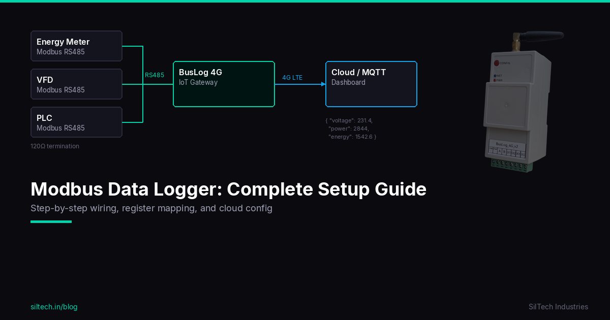
Most industrial devices — energy meters, VFDs, PLCs, temperature sensors — speak Modbus RTU over RS485. That's great for local SCADA, but useless if you need data in a cloud dashboard 200 km away. This guide covers the full process: wiring RS485, mapping registers, configuring a 4G gateway, and getting clean JSON into your MQTT broker.
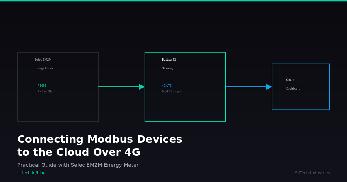
We'll use a Selec EM2M-1P-C-100A single-phase energy meter and a BusLog 4G gateway as the working example, but the concepts apply to any Modbus RTU device and cloud gateway.
What You Need
- Selec EM2M-1P-C-100A energy meter (or any Modbus RTU slave device)
- BusLog 4G gateway (or any 4G gateway with an RS485 port)
- RS485 cable — twisted pair, shielded for runs > 10m
- Device register map — included below for the EM2M
- SIM card — any LTE Cat-1 carrier with a data plan
RS485 Wiring Basics
RS485 uses differential signaling over two wires (A and B). Simple, but easy to mess up in the field.
Standard Connection
Gateway          Slave Device
  A ──────────────── A
  B ──────────────── B
  GND ────────────── GND
For multiple devices, daisy-chain them — don't use star topology. RS485 is a bus:
Gateway ──── Device 1 ──── Device 2 ──── Device 3
                                           ┃
                                         120Ω
                                        (termination)
Wiring Rules
| Rule | Why |
|---|---|
| Always connect GND | Floating ground = intermittent failures on long runs |
| Daisy-chain, not star | Star topology causes signal reflections |
| Use shielded cable for > 10m | Industrial environments have EMI everywhere |
| 120Ω termination at last device for > 50m | Prevents signal reflection on long buses |
| Max bus length: ~1200m at 9600 baud | Beyond this, consider repeaters |
| Max 32 devices per bus (standard drivers) | Some devices use 1/4 unit load, allowing 128 |
A/B Labelling Confusion
Different manufacturers label A and B differently. Some call A the non-inverting line (D+), others call it inverting (D−). If your first attempt at communication fails, swap A and B. It won't damage anything.
Understanding the Register Map
Before configuring anything, you need to know exactly which registers to read. This comes from your device's datasheet.
Modbus Register Types
| Type | Function Code | Datasheet Prefix | Access |
|---|---|---|---|
| Coils | FC01 / FC05 | 0xxxx | R/W |
| Discrete Inputs | FC02 | 1xxxx | Read only |
| Input Registers | FC04 | 3xxxx | Read only |
| Holding Registers | FC03 / FC06 | 4xxxx | R/W |
Selec EM2M-1P-C-100A Register Map
The EM2M is a single-phase (1Ø-2W) DIN rail energy meter with RS485 Modbus RTU output. It's self-powered from 176–276V AC with a 100A max current rating — a common choice for single-phase sub-metering in commercial buildings.
All measurement data uses Input Registers (FC04), with each parameter stored as Float32 across 2 registers:
| Parameter | Datasheet Register | Modbus Address | Hex |
|---|---|---|---|
| Total Active Energy (kWh) | 30000 | 0 | 0x00 |
| Total Reactive Energy (kVArh) | 30002 | 2 | 0x02 |
| Import Reactive Energy | 30004 | 4 | 0x04 |
| Export Reactive Energy | 30006 | 6 | 0x06 |
| Apparent Energy (kVAh) | 30008 | 8 | 0x08 |
| Active Power (kW) | 30010 | 10 | 0x0A |
| Reactive Power (kVAr) | 30012 | 12 | 0x0C |
| Apparent Power (kVA) | 30014 | 14 | 0x0E |
| Voltage L-N (V) | 30016 | 16 | 0x10 |
| Current (A) | 30018 | 18 | 0x12 |
| Power Factor | 30020 | 20 | 0x14 |
| Frequency (Hz) | 30022 | 22 | 0x16 |
| Max Demand Active Power | 30024 | 24 | 0x18 |
| Max Demand Reactive Power | 30026 | 26 | 0x1A |
| Max Demand Apparent Power | 30028 | 28 | 0x1C |
| Import Active Energy (kWh) | 30028 | 28 | 0x1C |
| Export Active Energy (kWh) | 30030 | 30 | 0x1E |
The critical conversion: Datasheet register 30000 = Modbus address 0. For the EM2M, the offset is 30000 (not 30001 as in some other meters). Always verify against the actual datasheet.
The EM2M also exposes writable configuration via Holding Registers (FC03/FC06):
| Parameter | Register | Range | Default |
|---|---|---|---|
| Slave ID | 40001 | 1–255 | 1 |
| Baud Rate | 40010 | 9600 / 19200 | 9600 |
| Parity | 40011 | None / Odd / Even | None |
| Stop Bit | 40012 | 1 / 2 | 1 |
Byte Order — Float Swapped (CDAB)
Float32 values occupy 2 registers (4 bytes). The order these bytes are transmitted varies by manufacturer:
| Byte Order | Notation | Common In |
|---|---|---|
| Mid-Big-Endian | CDAB | Selec meters, some Siemens devices |
| Big-Endian | ABCD | Schneider, ABB |
| Mid-Little-Endian | BADC | Rare |
| Little-Endian | DCBA | Some Asian meters |
The Selec EM2M uses CDAB (Float Swapped) byte order. This means the two 16-bit registers are word-swapped compared to standard big-endian. If you configure ABCD and get values like 4.567e+18 or other garbage, switch to CDAB. This is the most common configuration mistake with Selec meters.
Example: A voltage reading of 230.5V in CDAB byte order:
Register 16 (high word): 0x6680   → bytes C, D
Register 17 (low word):  0x4366   → bytes A, B
Reassembled as ABCD: 43 66 80 00 → Float32 = 230.5
Connecting Selec EM2M to BusLog 4G — Step by Step
This section walks through the complete physical and software setup.
Step 1: Physical Wiring
The Selec EM2M has terminals 5–8 for RS485 communication. Connect to the BusLog 4G RS485 port as follows:
   Selec EM2M                    BusLog 4G
   (Terminals)                   (RS485 Port)
   ┌──────────┐                  ┌──────────┐
   │  5 (A+)  │────────────────│  A        │
   │  6 (B-)  │────────────────│  B        │
   │  7 (GND) │────────────────│  GND      │
   │  8 (GND) │  (spare GND)    │           │
   └──────────┘                  └──────────┘

   Power: EM2M is self-powered from 176–276V AC mains
          BusLog 4G needs 9–24V DC supply
Tip: The EM2M's terminal 8 is a second GND — useful if you're daisy-chaining to another device downstream.
Step 2: BusLog 4G Configuration
Configure the BusLog 4G to poll the EM2M registers. Here's the JSON device profile:
{
  "device_name": "EM2M_DB_Panel_1",
  "slave_id": 1,
  "baud_rate": 9600,
  "parity": "none",
  "stop_bits": 1,
  "poll_interval_sec": 10,
  "registers": [
    {
      "name": "voltage",
      "function_code": 4,
      "address": 16,
      "count": 2,
      "data_type": "float32",
      "byte_order": "CDAB",
      "unit": "V"
    },
    {
      "name": "current",
      "function_code": 4,
      "address": 18,
      "count": 2,
      "data_type": "float32",
      "byte_order": "CDAB",
      "unit": "A"
    },
    {
      "name": "active_power",
      "function_code": 4,
      "address": 10,
      "count": 2,
      "data_type": "float32",
      "byte_order": "CDAB",
      "unit": "kW"
    },
    {
      "name": "power_factor",
      "function_code": 4,
      "address": 20,
      "count": 2,
      "data_type": "float32",
      "byte_order": "CDAB",
      "unit": ""
    },
    {
      "name": "frequency",
      "function_code": 4,
      "address": 22,
      "count": 2,
      "data_type": "float32",
      "byte_order": "CDAB",
      "unit": "Hz"
    },
    {
      "name": "total_kwh",
      "function_code": 4,
      "address": 0,
      "count": 2,
      "data_type": "float32",
      "byte_order": "CDAB",
      "unit": "kWh"
    }
  ]
}
Key fields:
slave_id— must match the EM2M's configured address (default: 1, changeable via Holding Register 40001)address— 0-indexed Modbus address. For the EM2M, subtract 30000 from the datasheet register numbercount— always 2 for Float32 parametersbyte_order— CDAB for all Selec EM2M registerspoll_interval_sec— 10s is a good default; energy meters don't change faster than that
Step 3: What Happens on the Wire
When the gateway polls voltage from the EM2M (FC04, address 16, count 2), here's the actual Modbus RTU frame:
Request:  01 04 00 10 00 02 70 06
          ── ── ───── ───── ─────
          ID FC Addr  Count CRC16
          │  │  │     │     └─ CRC-16 (Modbus)
          │  │  │     └─ Read 2 registers (Float32)
          │  │  └─ Address 16 = 0x0010 (Voltage L-N)
          │  └─ FC04 = Read Input Registers
          └─ Slave ID 1

Response: 01 04 04 66 80 43 66 XX XX
          ── ── ── ─────────── ─────
          ID FC Len  Data(4B)  CRC16
The 4 data bytes 66 80 43 66 are in CDAB order. Reassemble to ABCD: 43 66 80 00 → Float32 = 230.5V. That's your voltage reading.
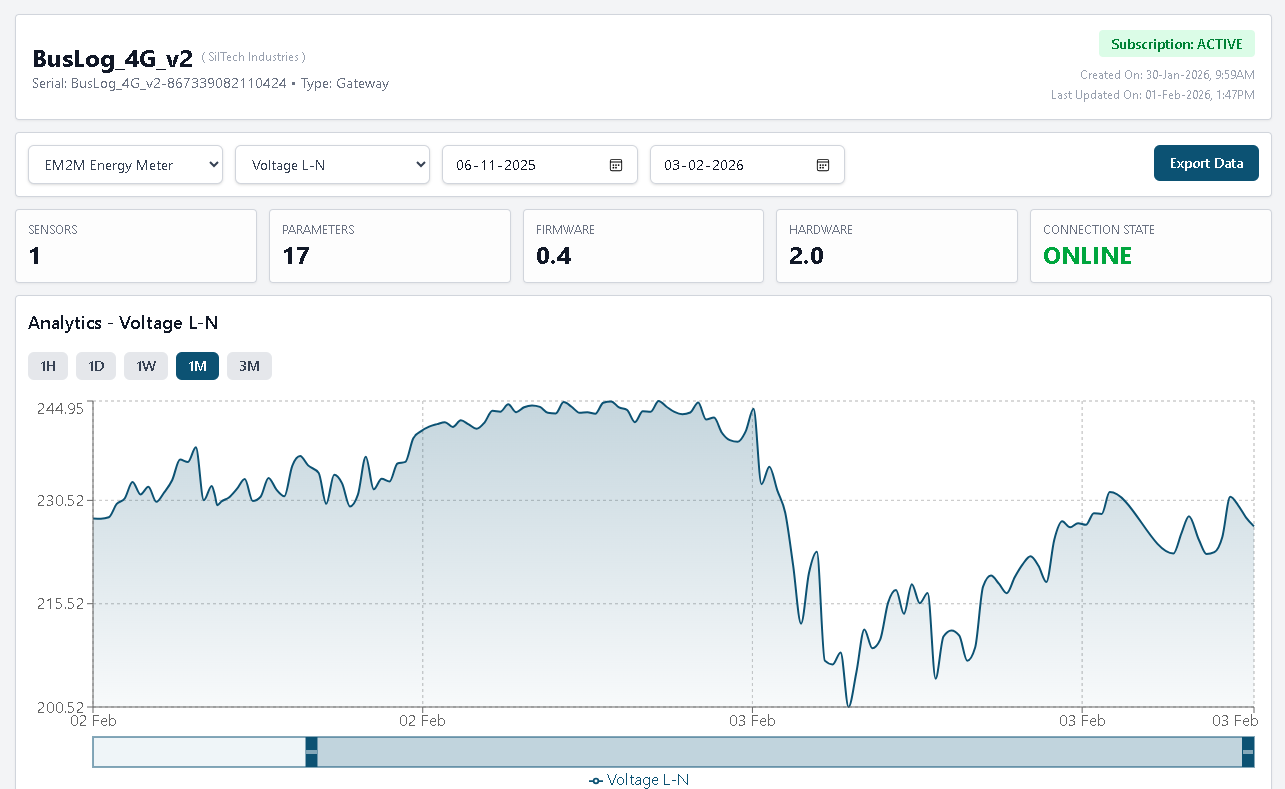
Step 4: Data in the Cloud
Once the gateway reads successfully, it pushes JSON over MQTT via 4G:
Topic:   siltech/{gateway_serial}/data
Payload:
{
  "ts": 1708243200,
  "device": "EM2M_DB_Panel_1",
  "voltage": 230.5,
  "current": 4.21,
  "active_power": 0.97,
  "power_factor": 0.99,
  "frequency": 50.01,
  "total_kwh": 14523.7
}
The gateway buffers data in internal memory during network outages and auto-uploads when 4G reconnects — no data loss even if cellular drops for hours.
From your MQTT broker, route this to any platform: Grafana, ThingsBoard, AWS IoT, Node-RED, or your own backend. It's standard JSON over standard MQTT.
Gotchas / Debugging
These are the problems we see repeatedly across thousands of field deployments.
CRC Errors / No Response
| Symptom | Likely Cause | Fix |
|---|---|---|
| TX LED blinks, RX doesn't | Slave not responding | Check slave ID, baud rate, parity. Try swapping A/B |
| Intermittent timeouts | Loose wiring or EMI | Check screw terminals, use shielded cable |
| Works on bench, fails on site | Ground potential difference | Connect GND wire between gateway and device |
Wrong Values
| Symptom | Likely Cause | Fix |
|---|---|---|
| Always 0 or 65535 | Wrong register address | Verify off-by-one: subtract 30000 for EM2M (not 30001) |
| Very large/small numbers | Wrong byte order | EM2M uses CDAB — not ABCD |
| Values half of expected | Wrong data type (Int16 vs Float32) | Check count — should be 2 for Float32 |
| Negative when should be positive | Signed vs unsigned mismatch | Switch int16 to uint16 |
Bus Problems at Scale
- More than 3-4 devices: Increase inter-frame delay (silent interval) to avoid collisions
- Devices from different manufacturers: They may default to different baud rates — standardise everything to 9600/8N1 before connecting
- Long cable runs (> 100m): Always terminate, always shield, always ground
- Intermittent failures in summer: Thermal expansion loosens screw terminals. Use ferrules on wire ends
4G Connectivity Issues
- No signal: Check antenna connection. The small PCB antenna works for most sites; use an external antenna for basements or metal enclosures
- Connects but no data: Verify MQTT broker address and port. Check SIM data balance
- Auto-APN not working: BusLog auto-detects Indian carriers. For private APNs, configure manually via the portal
Quick Reference / Checklist
Use this before every deployment:
Physical Setup
- [ ] RS485 A, B, GND wired correctly (EM2M terminals 5, 6, 7 → BusLog A, B, GND)
- [ ] Daisy-chain topology (not star)
- [ ] 120Ω termination on last device (if cable > 50m)
- [ ] Shielded cable for runs > 10m
- [ ] SIM card inserted, antenna connected
- [ ] Power supply: 9–24V DC to gateway, 176–276V AC to EM2M
Configuration
- [ ] Slave ID matches EM2M setting (default: 1)
- [ ] Baud rate 9600, parity None, stop bits 1 (EM2M defaults)
- [ ] Register addresses are 0-indexed (subtract 30000 for EM2M)
- [ ] Function code: FC04 for all measurement registers
- [ ] Byte order set to CDAB (Float Swapped) for all EM2M registers
- [ ] MQTT broker address and credentials configured
Verification
- [ ] TX LED blinking = gateway polling
- [ ] RX LED blinking = EM2M responding
- [ ] Cloud dashboard shows expected values with correct units
- [ ] Simulate a network drop and verify data buffering/recovery
Next Steps
- Need to monitor multiple EM2M meters on one bus? See our guide on multi-device RS485 deployments (coming soon)
- Battery-powered remote site? Check the BusLog 4G BAT for deep-sleep operation
- Need Modbus TCP + RTU? The BusLog IO UNI supports both plus Ethernet
- Questions? Contact our engineering team
Based on field experience from 4500+ BusLog deployments across India. Found an error or have a suggestion? Let us know — we update our guides based on real feedback.